Программа
6 типов файлов, которые можно удалить с телефона, если не хватает памяти Рано или поздно любой владелец смартфона сталкивается с тем, что встроенное хранилище, а… Подробнее » Gr6da7 что это большие файлы на телефоне
Hard disk 3f0 что делать
- автор: admin
- 05.07.2023
[Решено] Ошибка жесткого диска 3f0, загрузочное устройство не найдено на HP Некоторые владельцы ноутбуков HP сообщали об ошибке с кодом 3f0 при загрузке своих систем.… Подробнее » Hard disk 3f0 что делать
Hamachi failed to connect to the engine что делать mac
- автор: admin
- 05.07.2023
Hamachi failed to connect to the engine что делать mac Hamachi failed to connect to the engine что делать mac LogMeIn support sites no longer… Подробнее » Hamachi failed to connect to the engine что делать mac
Hd 4000 на сколько хватает
- автор: admin
- 05.07.2023
Электронная сигарета HQD Cuvie AIR Disposable Vape, технические параметры, дизайн Одноразовые электронные сигареты часто помогают тем, кто борется с табачной зависимостью. Поскольку такие устройства просты… Подробнее » Hd 4000 на сколько хватает
Hardware ecc recovered victoria что значит
- автор: admin
- 05.07.2023
Victoria. Восстановление работоспособности жесткого диска. Восстановить жесткий диск, используя специальные программы. Они позволяют протестировать винчестер, а также исправить незначительные неисправности. Зачастую, этого вполне достаточно для… Подробнее » Hardware ecc recovered victoria что значит
Biostar H61MHV2 Manual
This equipment has been tested and found to comply with the limits of a Class B digital device, pursuant to Part 15 of the FCC Rules. These limits are designed to provide reasonable protection against harmful interference in a residential installation. This equipment generates, uses, and can radiate radio frequency energy and, if not installed and used in accordance with the instructions, may cause harmful interference to radio communications. There is no guarantee that interference will not occur in a particular installation.
The vendor makes no representations or warranties with respect to the contents here and specially disclaims any implied warranties of merchantability or fitness for any purpose. Further the vendor reserves the right to revise this publication and to make changes to the contents here without obligation to notify any party beforehand.
Duplication of this publication, in part or in whole, is not allowed without first obtaining the vendor’s approval in writing.
The content of this user’s manual is subject to be changed without notice and we will not be responsible for any mistakes found in this user’s manual. All the brand and product names are trademarks of their respective companies.
Dichiarazione di conformità sintetica
Ai sensi dell’art. 2 comma 3 del D.M. 275 del 30/10/2002
Si dichiara che questo prodotto è conforme alle normative vigenti e soddisfa i requisiti essenziali richiesti dalle direttive
2004/108/CE, 2006/95/CE e 1999/05/CE
quando ad esso applicabili
Short Declaration of conformity
We declare this product is complying with the laws in force and meeting all the essential requirements as specified by the directives
2004/108/CE, 2006/95/CE and 1999/05/CE
whenever these laws may be applied
Table of Contents
Chapter 1: Introduction.
BIOSTAR H61MHV2 Motherboard User Manual
Thank you for choosing our product. Before you start installing the motherboard, please make sure you follow the instructions below:
- Prepare a dry and stable working environment with sufficient lighting.
- Always disconnect the computer from power outlet before operation.
- Before you take the motherboard out from anti-static bag, ground yourself properly by touching any safely grounded appliance, or use grounded wrist strap to remove the static charge.
- Avoid touching the components on motherboard or the rear side of the board unless necessary. Hold the board on the edge, do not try to bend or flex the board.
- Do not leave any unfastened small parts inside the case after installation. Loose parts will cause short circuits which may damage the equipment.
- Keep the computer from dangerous area, such as heat source, humid air and water.
- The operating temperatures of the computer should be 0 to 45 degrees Celsius.
- To avoid injury, be careful of:
- Sharp pins on headers and connectors
- Rough edges and sharp corners on the chassis
- Damage to wires that could cause a short circuit
PACKAGE CHECKLIST
- Serial ATA Cable x2
- Rear I/O Panel for ATX Case x1
- Quick Installation Guide x1
- Fully Setup Driver DVD x1
- Note: The package contents may be different due to the sales region or models in which it was sold. For more information about the standard package in your region, please contact your dealer or sales representative.
MOTHERBOARD FEATURES
SPEC
Intel Core i7 / i5 / i3 / Pentium / Celeron processor
| Supports Execute Disable Bit / Enhanced Intel SpeedStep® / Intel Architecture-64 / Extended Memory 64 Technology / Virtualization Technology /
Chipset| Intel H61|
Provides the most commonly used legacy Super I/O functionality
Low Pin Count Interface
| Environment Control initiatives Hardware Monitor Controller Fan Speed Controller
ITE’s “Smart Guardian” function
| DDR3 DIMM Slots x 2| Dual Channel Mode DDR3 memory module
Main| Max Memory Capacity 16GB| Supports DDR3 1066 / 1333
Memory| Each DIMM supports 512MB/| Supports DDR3 1600 (depending on CPU)
| 1GB/2GB/4GB/8GB DDR3| Registered DIMM and ECC DIMM is not supported
Integrated Serial ATA Controller
| Data transfer rates up to 3.0 Gb/s
SATA Version 2.0 specification compliant
LAN| RTL8111H| 10 / 100 / 1000Mb/s auto negotiation
Sound Codec| ****
5.1 channels audio out , High Definition Audio
| PCI-E Gen3x16 slot (depending on CPU)
PCI-E Gen2 x1 slot
| Supports PCI-E Gen2/3 x16 expansion card
Supports PCI-E Gen2 x1 expansion card
On Board Connectors
| SATA2 Connector Front Panel Connector
Chassis Speaker Connector Front Audio Connector
CPU Fan Header System Fan Header Clear CMOS Header
| x4 x1 x1 x1 x1 x1 x1
| Each connector supports 1 SATA2 device Supports front panel facilities
Supports chassis speaker Supports front panel audio function
CPU Fan power supply (with Smart Fan function) System Fan Power supply
Restore CMOS data to factory default
Each connector supports 2 front panel USB2.0 ports
| Serial Port Connector| x1| Connects to RS-232 Port
| Power Connector (24pin) Power Connector (4pin)| x1 x1| Connects to Power supply Connects to Power supply
| PS/2 Keyboard/ Mouse| x1| Connects to PS/2 Keyboard & Mouse
| VGA Port| x1| Connect to D-SUB monitor
Rear Panel| HDMI Port| x1| Connect to HDMI monitor
I/O| LAN port| x1| Connect to RJ-45 Ethernet cable
| USB2.0 Port| x4| Connect to USB2.0 devices
| Audio Jack| x3| Provide Audio-In/Out and Mic. Connection
Board Size| 170 (W) x 191 (L) mm|
Windows XP / Vista / 7 / 8 / 8.1 / 10
| Biostar reserves the right to add or remove support
for any OS with or without notice
REAR PANEL CONNECTORS

- Note1: VGA Output requires an Intel Core family processor with Intel Graphics Technology.
- Note2: VGA Maximum resolution: 2048 x 1536 @75Hz
MOTHERBOARD LAYOUT
Note 1: represents the 1st pin.
HARDWARE INSTALLATION
INSTALLING A CENTRAL PROCESSING UNIT (CPU)
Step 1: Locate the CPU socket on the motherboard

- Note 1: Remove the Pin Cap before installation, and make good preservation for future use. When the CPU is removed, cover the Pin Cap on the empty socket to ensure the pin legs won’t be damaged.
- Note 2: The motherboard might equip with two different types of pin caps. Please refer below instruction to remove the pin cap.
- Step 2: Pull the socket locking lever out from the socket and then raise the lever up.
- Step 4: Hold the processor with your thumb and index fingers, oriented as shown. Align the notches with the socket. Lower the processor straight down without tilting or sliding the processor in the socket.
- Note: The CPU fits only in one correct orientation. Do not force the CPU into the socket to prevent damaging the CPU.
- Step 5: Hold the CPU down firmly, and then lower the lever to a locked position to complete the installation.
INSTALL A HEATSINK
- Step 1: Place the CPU fan assembly on top of the installed CPU and make sure that the four fasteners match the motherboard holes. Orient the assembly and make the fan cable closest to the CPU fan connector.
- Step 2: Press down two fasteners at one time in a diagonal sequence to secure the CPU fan assembly in place. Ensure that all four fasteners are secured.
- Note 1: Do not forget to connect the CPU fan connector.
- Note 2: For proper installation, please kindly refer to the installation manual of your CPU heatsink.
FAN HEADERS
- These fan headers support cooling-fans built in the computer. The fan cable and connector may be different according to the fan manufacturer. Connect the fan cable to the connector while matching the black wire to pin#1.
CPU_FAN1: CPU Fan Header
| Pin | Assignment |
|---|---|
| 1 | Ground |
| 2 | +12V |
| 3 | FAN RPM rate since |
| 4 | Smart Fan Control (By Fan) |
SYS_FAN1: System Fan Header
| Pin | Assignment |
|---|---|
| 1 | Ground |
| 2 | +12V |
| 3 | FAN RPM rate sense |
Note: CPU_FAN1 support 4-pin and 3-pin head connectors. When connecting with wires onto connectors, please note that the red wire is the positive and should be connected to pin#2, and the black wire is Ground and should be connected to GND. SYS_FAN3 support 3-pin head connectors. When connecting with wires onto connectors, please note that the red wire is the positive and should be connected to pin#2, and the black wire is Ground and should be connected to GND.
INSTALLING SYSTEM MEMORY

- A. Memory Modules
- Step 1: Unlock a DIMM slot by pressing the retaining clips outward. Align a DIMM on the slot such that the notch on the DIMM matches the break on the slot.
- Step 2: Insert the DIMM vertically and firmly into the slot until the retaining chip snaps back in place and the DIMM is properly seated.
Note: If the DIMM does not go in smoothly, do not force it. Pull it all the way out and try again.
B. Memory Capacity
| DIMM Socket Location | DDR3 Module | Total Memory Size |
|---|---|---|
| DDR3_A1 | 512MB/1GB/2GB/4GB/8GB | **** |
C. Dual Channel Memory Installation
Please refer to the following requirements to activate the Dual Channel function: Install a memory module of the same density in pairs, shown in the table.
| Dual Channel Status | DDR3_A1 | DDR3_B1 |
|---|---|---|
| Disabled | O | X |
| Disabled | X | O |
| Enabled | O | O |
(O means memory installed; X, not installed.)
Note: The DRAM bus width of the memory module must be the same (x8 or x16)
CONNECTORS AND SLOTS
SATA1~SATA4: Serial ATA Connectors
- These connectors connect to SATA hard disk drives via SATA cables.
- Those satisfy the SATA 2.0 spec and with a transfer rate of 3.0Gb/s.
| Pin | Assignment |
|---|---|
| 1 | Ground |
| 2 | TX+ |
| 3 | TX- |
| 4 | Ground |
| 5 | RX- |
| 6 | RX+ |
| 7 | Ground |
ATXPWR2: ATX Power Source Connector
This connector provides +12V to a CPU power circuit.
| Pin | Assignment |
|---|---|
| 1 | +12V |
| 2 | +12V |
| 3 | Ground |
| 4 | Ground |
ATXPWR1: ATX Power Source Connector
This connector allows user to connect 24-pin power connector on the ATX power supply.
| Pin | Assignment | Pin | Assignment |
|---|---|---|---|
| 13 | +3.3V | 1 | +3.3V |
| 14 | -12V | 2 | +3.3V |
| 15 | Ground | 3 | Ground |
| 16 | PS_ON | 4 | +5V |
| 17 | Ground | 5 | Ground |
| 18 | Ground | 6 | +5V |
| 19 | Ground | 7 | Ground |
| 20 | NC | 8 | PW_OK |
| 21 | +5V | 9 | Standby Voltage+5V |
| 22 | +5V | 10 | +12V |
| 23 | +5V | 11 | +12V |
| 24 | Ground | 12 | +3.3V |
- Note1: Before you power on the system, please make sure that both ATXPWR1 and ATXPWR2 connectors have been plugged-in.
- Note 2: Insufficient power supplied to the system may result in instability or the peripherals not functioning properly. Use of a PSU with a higher power output is recommended when configuring a system with more power-consuming devices.
PEX16_1: PCI-Express Gen3 x16 Slot
- PCI-Express 3.0 compliant.
- Maximum theoretical realized bandwidth of 16GB/s simultaneously per direction, for an aggregate of 32GB/s totally.
- PCI-E 3.0 is supported by Core i7-3xxx / i5-3xxx CPU.
PEX1_1: PCI-Express Gen2 x1 Slot

- PCI-Express 2.0 compliant.
- Data transfer bandwidth up to 500MB/s per direction; 1GB/s in total.
Install an Expansion Card
You can install your expansion card by following the steps:
- Read the related expansion card’s instruction document before installing the expansion card into the computer.
- Remove your computer’s chassis cover, screws, and slot bracket from the computer.
- Place a card in the expansion slot and press down on the card until it is completely seated in the slot.
- Secure the card’s metal bracket to the chassis back panel with a screw.
- Replace your computer’s chassis cover.
- Power on the computer, and if necessary, change BIOS settings for the expansion card.
- Install the related driver for the expansion card.
HEADERS & JUMPERS SETUP
HOW TO SETUP JUMPERS

- The illustration shows how to set up jumpers. When the jumper cap is placed on pins, the jumper is “close”, if not, that means the jumper is “open”.
DETAIL SETTINGS
JPANEL1: Front Panel Header
- This connector includes Power-on, Reset, HDD LED, and Power LED connections. It allows the user to connect the PC case’s front panel switch functions.
Pin| Assignment| Function| Pin| Assignment| Function
—|—|—|—|—|—
1| N/A| N/A| 2| Power LED (+)|
3| HDD LED(+)| HDD LED| 4| Power LED (+)
5| HDD LED(-)| 6| Power LED (-)
7| Ground| Reset Button| 8| Power Button| Power-On Button
9| Reset Control| 10| Ground
JSPKR1: Chassis Speaker Header
Please connect the chassis speaker to this header.
| Pin | Assignment |
|---|---|
| 1 | +5V |
| 2 | N/A |
| 3 | N/A |
| 4 | Speaker |
F_USB1/F_USB2: Headers for USB 2.0 Ports at Front Panel
These headers allow users to connect additional USB cable on the PC front panel, and also can be connected with internal USB devices, like USB card reader.
| Pin | Assignment |
|---|---|
| 1 | +5V (fused) |
| 2 | +5V (fused) |
| 3 | USB- |
| 4 | USB- |
| 5 | USB+ |
| 6 | USB+ |
| 7 | Ground |
| 8 | Ground |
| 9 | Key |
| 10 | NC |
J_COM1: Serial Port Connector
The motherboard has a Serial Port Connector for connecting RS-232 Port.
| Pin | Assignment |
|---|---|
| 1 | Carrier detect |
| 2 | Received data |
| 3 | Transmitted data |
| 4 | Data terminal ready |
| 5 | Signal ground |
| 6 | Data set ready |
| 7 | Request to send |
| 8 | Clear to send |
| 9 | Ring indicator |
| 10 | Key |
F_AUDIO1: Front Panel Audio Header
This header allows users to connect the front audio output cable with the PC front panel.
| HD Audio | AC’97 |
|---|---|
| Pin | Assignment |
| 1 | Mic Left in |
| 2 | Ground |
| 3 | Mic Right in |
| 4 | GPIO |
| 5 | Right line in |
| 6 | Jack Sense |
| 7 | Front Sense |
| 8 | Key |
| 9 | Left line in |
| 10 | Jack Sense |
- Note 1: It is recommended that you connect a high-definition front panel audio module to this connector to avail of the motherboard’s high-definition audio capability.
- Note 2: Please try to disable the “Front Panel Jack Detection” if you want to use an AC’97 front audio output cable. The function can be found via O.S. Audio Utility.
JCMOS1: Clear CMOS Jumper
- The jumper allows users to restore the BIOS safe setting and the CMOS data.
- Please carefully follow the procedures to avoid damaging the motherboard.
Clear CMOS Procedures:
- Remove AC power line.
- Set the jumper to “Pin 1-2 close”, you can use a metal object like a screwdriver to touch the two pins.
- Wait for five seconds.
- After clearing the CMOS values, be sure the jumper is “Pin 1-2 open”.
- Power on the AC.
- Load Optimal Defaults and save settings in CMOS.
USEFUL HELP
DRIVER INSTALLATION NOTE
- After you installed your operating system, please insert the Fully Setup Driver
- DVD into your optical drive and install the driver for better system performance.
- You will see the following window after you insert the DVD
- The setup guide will auto detect your motherboard and operating system.
Note: If this window didn’t show up after you insert the Driver DVD, please use file browser to locate and execute the file SETUP.EXE under your optical drive.
A. Driver Installation
- To install the driver, please click on the Driver icon. The setup guide will list the compatible driver for your motherboard and operating system. Click on each device driver to launch the installation program.
B. Software Installation
- To install the software, please click on the Software icon. The setup guide will list the software available for your system, click on each software title to launch the installation program.
C. Manual
- Aside from the paperback manual, we also provide manual in the Driver DVD.
- Click on the Manual icon to browse for available manual.
- Note: You will need Acrobat Reader to open the manual file. Please download the latest version of Acrobat Reader software from http://get.adobe.com/reader/
BIOS UPDATE
- There are three ways to update the BIOS: BIOSTAR BIOS Flasher.
- Note: The programming procedure may take minutes, please do not make any operation during the programming process.
BIOSTAR BIOS Flasher
- BIOSTAR BIOS Flasher is a BIOS flashing utility providing you an easy and simple way to update your BIOS via USB pen drive.
- The BIOSTAR BIOS Flasher is built in the BIOS ROM. To enter the utility, press during the Power-On Self Tests (POST) procedure while booting up.
- Note1: This utility only allows storage device with FAT32/16 format and single partition.
- Note 2: Shutting down or resetting the system while updating the BIOS will lead to system boot failure.
Updating BIOS with BIOSTAR BIOS Flasher

- Go to the website to download the latest BIOS file for the motherboard.
- Then, copy and save the BIOS file into a USB flash (pen) drive.
- Insert the USB pen drive that contains the BIOS file to the USB port.
- Power on or reset the computer and then press during the POST process.
- After entering the POST screen, the BIOS-FLASHER utility pops out. Choose [fs0] to search for the BIOS file.
- Select the proper BIOS file, and a message asking if you are sure to flash the BIOS file. Click Yes to start updating BIOS.
- A dialog pops out after BIOS flash is completed, asking you to restart the system. Press the [Y] key to restart system.
- While the system boots up and the full-screen logo shows up, press the key to enter BIOS setup. After entering the BIOS setup, please go to the Save & Exit, using the Restore Defaults function to load Optimized Defaults, and select Save Changes and Reset to restart the computer. Then, the BIOS Update is completed.
AMI BIOS BEEP CODE
Boot Block Beep Codes
| Number of Beeps | Description |
|---|---|
| Continuing | Memory sizing error or Memory module not found |
POST BIOS Beep Codes
| Number of Beeps | Description |
|---|---|
| 1 | Success booting. |
| 8 | Display memory error (system video adapter) |
TROUBLESHOOTING
| Probable | Solution |
|---|
1. There is no power in the system. Power LED does not shine; the fan of the power supply does not work
2. Indicator light on keyboard does not shine.
| 1. Make sure power cable is securely plugged in.
2. Replace cable.
3. Contact technical support.
System is inoperative. Keyboard lights are on, power indicator lights are lit, and hard drives are running.| Using even pressure on both ends of the DIMM, press down firmly until the module snaps into place.
System does not boot from a hard disk drive, but can be booted from optical drive.| 1. Check cable running from disk to disk controller board. Make sure both ends are securely plugged in; check the drive type in the standard CMOS setup.
2. Backing up the hard drive is extremely important. All hard disks are capable of breaking down at any time.
System only boots from an optical drive. Hard disks can be read, applications can be used, but system fails to boot from a hard disk.| 1. Back up data and applications files.
2. Reformat the hard drive. Re-install applications and data using backup disks.
Screen message shows “Invalid Configuration” or “CMOS Failure.”| Review system’s equipment. Make sure correct information is in setup.
System cannot boot after the user installs a second hard drive.| 1. Set master/slave jumpers correctly.
2. Run SETUP program and select correct drive types. Call the drive manufacturers for compatibility with other drives.
CPU Overheated
- If the system shutdown automatically after power on system for seconds, that means the CPU protection function has been activated.
- When the CPU is over heated, the motherboard will shutdown automatically to avoid a damage of the CPU, and the system may not power on again.
In this case, please double check:
- The CPU cooler surface is placed evenly with the CPU surface.
- CPU fan is rotated normally.
- CPU fan speed is fulfilling with the CPU speed.
After confirmed, please follow steps below to relief the CPU protection function.
- Remove the power cord from power supply for seconds.
- Wait for seconds.
- Plug in the power cord and boot up the system.
Or you can:
- Clear the CMOS data. (See “Close CMOS Header: JCMOS1” section)
- Wait for seconds.
- Power on the system again.
FCC
Information and Copyright
- This equipment has been tested and found to comply with the limits of a Class B digital device, pursuant to Part 15 of the FCC Rules. These limits are designed to provide reasonable protection against harmful interference in a residential installation. This equipment generates, uses, and can radiate radio frequency energy and, if not installed and used in accordance with the instructions, may cause harmful interference to radio communications. There is no guarantee that interference will not occur in a particular installation.
- The vendor makes no representations or warranties with respect to the contents here and specially disclaims any implied warranties of merchantability or fitness for any purpose. Further the vendor reserves the right to revise this publication and to make changes to the contents here without obligation to notify any party beforehand.
- Duplication of this publication, in part or in whole, is not allowed without first obtaining the vendor’s approval in writing.
- The content of this user’s manual is subject to be changed without notice and we will not be responsible for any mistakes found in this user’s manual. All the brand and product names are trademarks of their respective companies.
Dichiarazione di conformità sintetica
- Ai sensi dell’art. 2 comma 3 del D.M. 275 del 30/10/2002 Si dichiara che questo prodotto è conforme alle normative vigenti e soddisfa i requisiti essenziali richiesti dalle directive 2004/108/CE, 2006/95/CE e 1999/05/CE quando ad esso applicabili
Short Declaration of conformity
- We declare this product is complying with the laws in force and meeting all the essential requirements as specified by the directives 2004/108/CE, 2006/95/CE and 1999/05/CE whenever these laws may be applied
References
H61mhv2 как переключить на 1333мг
This equipment has been tested and found to comply with the limits of a Class B digital device, pursuant to Part 15 of the FCC Rules. These limits are designed to provide reasonable protection against harmful interference in a residential installation. This equipment generates, uses, and can radiate radio frequency energy and, if not installed and used in accordance with the instructions, may cause harmful interference to radio communications. There is no guarantee that interference will not occur in a particular installation.
The vendor makes no representations or warranties with respect to the contents here and specially disclaims any implied warranties of merchantability or fitness for any purpose. Further the vendor reserves the right to revise this publication and to make changes to the contents here without obligation to notify any party beforehand.
Duplication of this publication, in part or in whole, is not allowed without first obtaining the vendor’s approval in writing.
The content of this user’s manual is subject to be changed without notice and we will not be responsible for any mistakes found in this user’s manual. All the brand and product names are trademarks of their respective companies.
Dichiarazione di conformità sintetica
Ai sensi dell’art. 2 comma 3 del D.M. 275 del 30/10/2002
Si dichiara che questo prodotto è conforme alle normative vigenti e soddisfa i requisiti essenziali richiesti dalle direttive
2004/108/CE, 2006/95/CE e 1999/05/CE
quando ad esso applicabili
Short Declaration of conformity
We declare this product is complying with the laws in force and meeting all the essential requirements as specified by the directives
H61mhv2 как переключить на 1333мг

Продвинутым пользователям хорошо известен термин «разгон», который подразумевает увеличение производительности того или иного компонента компьютера свыше штатного режима. Процедура разгона оперативной памяти включает в себя ручную установку рабочей частоты модулей, о чём мы сегодня и хотим поговорить.
Видео инструкция
Выбор частоты ОЗУ
Прежде, чем приступить к увеличению частоты памяти, отметим несколько важных моментов.
- Далеко не все материнские платы поддерживают такую функцию: чаще всего настройка частоты попадается в моделях, нацеленных на геймеров или компьютерных энтузиастов. Также подобные настройки обычно отсутствуют в ноутбуках.
- Обязательно нужно учитывать тип установленной RAM, особенно в БИОСах, где есть возможность вручную прописать значение частоты.
- Повышенные частоты обычно сопровождаются и повышением выделяемого тепла, поэтому строго рекомендуется установить серьёзное охлаждение.
Собственно процедура увеличения memory frequency отличается от типа BIOS, установленного на плату.
Внимание! Для полноценного разгона оперативной памяти просто увеличить частоту недостаточно – потребуется также изменить некоторые другие параметры вроде таймингов и вольтажа! Об этом рассказано в отдельном материале!
Рассмотрим на примерах наиболее распространённых вариантов. Разумеется, сперва в БИОС нужно зайти – в статье по ссылке ниже вы найдёте детальное руководство по входу в интерфейс микропрограммы.
Текстовый вариант
Классические текстовые БИОС с управлением с клавиатуры уходят в прошлое, но для некоторых пользователей всё ещё актуальны.
AMI
-
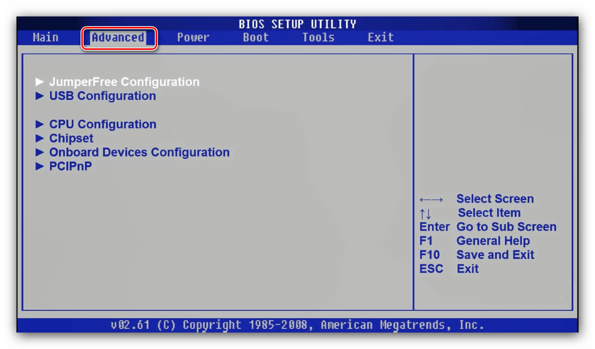
Войдите в интерфейс прошивки и перейдите на вкладку «Advanced».
Award
-
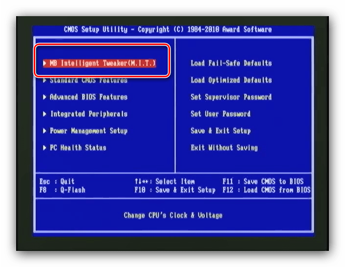
В главном меню BIOS воспользуйтесь опцией «MB Intelligent Tweaker».

Phoenix
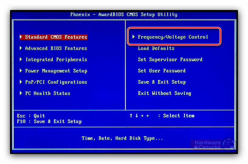
- В главном меню выберите вариант «Frequency/Voltage Control».
- Далее воспользуйтесь меню «Memory Feature».
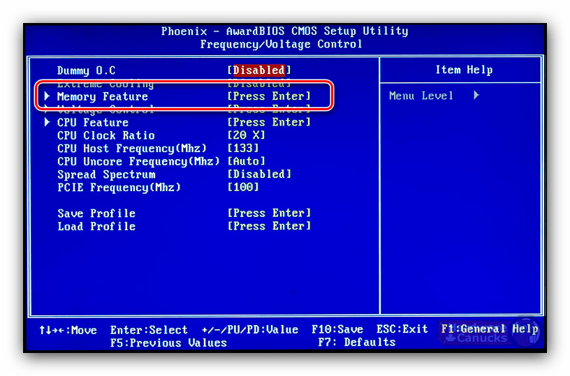
- Найдите опцию «Memory Control Setting», её нужно установить в положение «Enable». Далее откройте меню «Memory Frequency» – установите желаемую частоту с помощью стрелок и клавиши Enter.
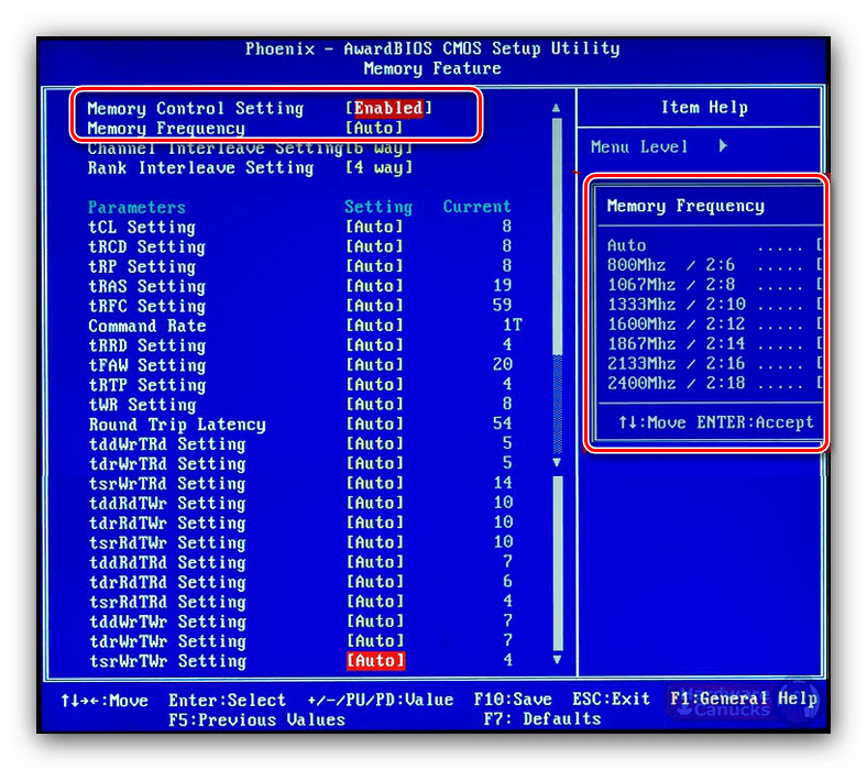
- Настройте остальные параметры, если это необходимо, затем задействуйте клавишу F10 для сохранения изменений.
Обращаем ваше внимание – в некоторых случаях опции в каждом из рассматриваемых БИОС могут менять название или местоположение – зависит от производителя материнской платы.
Графическая оболочка
Практически все современные продвинутые платы идут с графическим UEFI-интерфейсом, более удобным в освоении. Следовательно, настройка тактовой частоты RAM в подобных вариантах микропрограммы достаточно простая.
ASRock
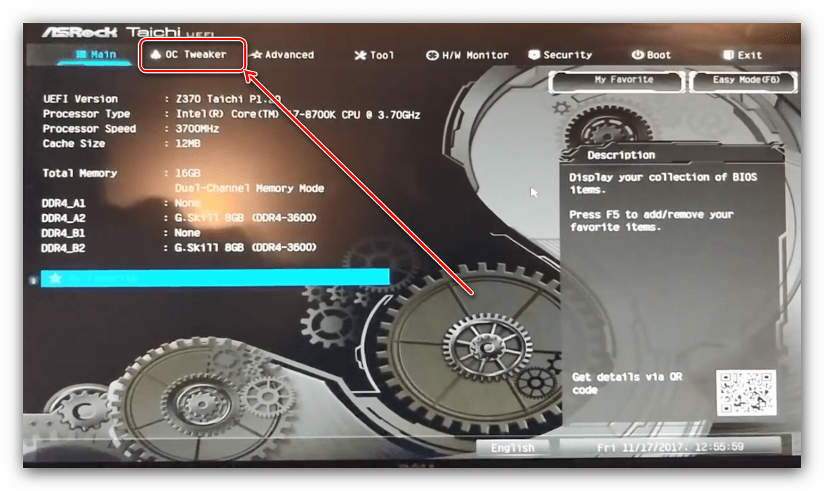
- Перейдите в Advanced Mode нажатием на клавишу F6.
- Откройте закладку «OC Tweaker», где воспользуйтесь меню «DRAM Configuration».
- Зайдите в меню «DRAM Frequency» – появится список с доступными частотами, соответствующими типу ОЗУ. Выберите подходящий.
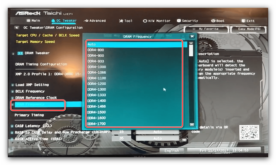
- Также скорректируйте тайминги, если считаете нужным, и переходите к вкладке «Exit». Воспользуйтесь пунктом «Save Changes & Exit» и подтвердите выход из интерфейса.
ASUS
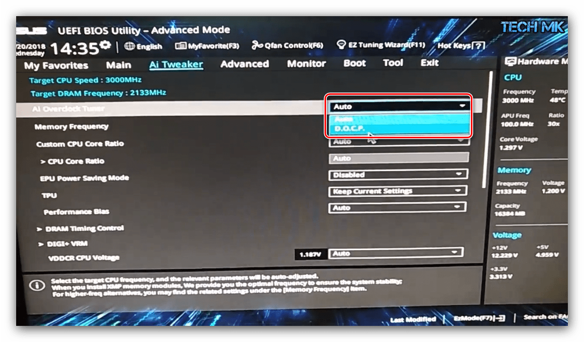
- После загрузки БИОСа нажмите клавишу F7 для перехода в продвинутый режим.
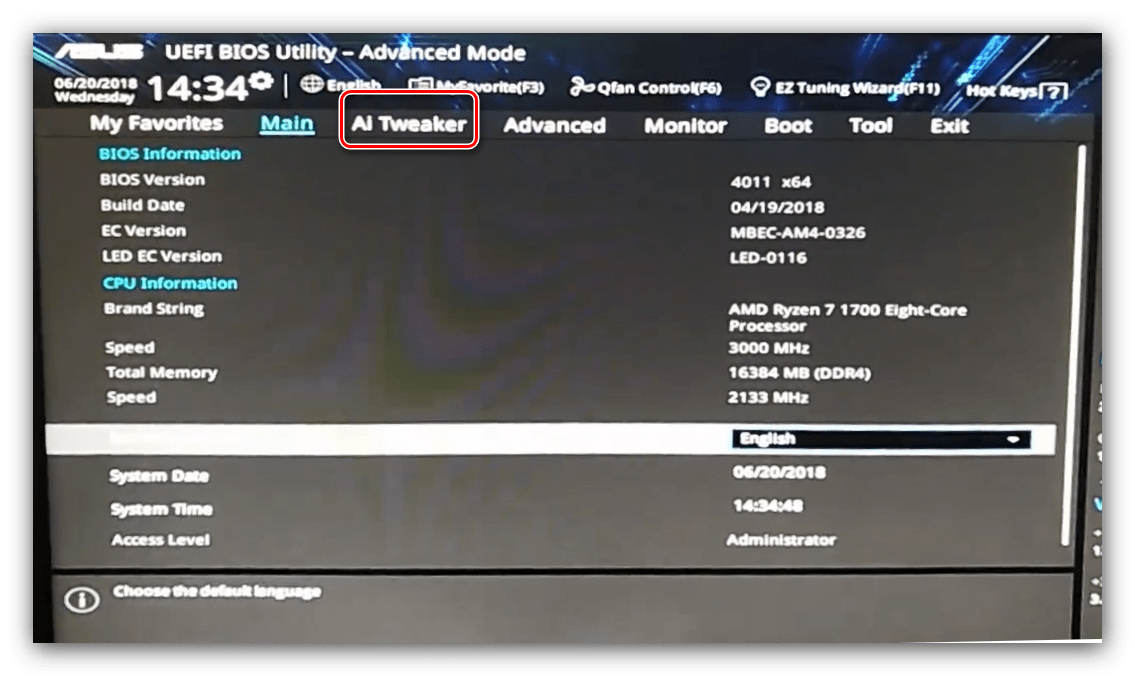
- В продвинутом режиме перейдите ко вкладке «AI Tweaker» (в некоторых вариантах плат называется «Extreme Tweaker»). Первым делом установите опцию «AI Overclock Tuner» в положение «D.O.C.P.».
- Далее воспользуйтесь опцией «Memory Frequency». Появится всплывающее меню, в котором выберите подходящее значение для вашего типа оперативной памяти.
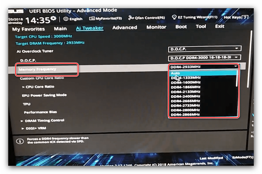
- Воспользуйтесь кнопкой «Save & Exit», чтобы применить изменения.
Gigabyte
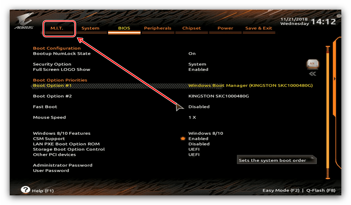
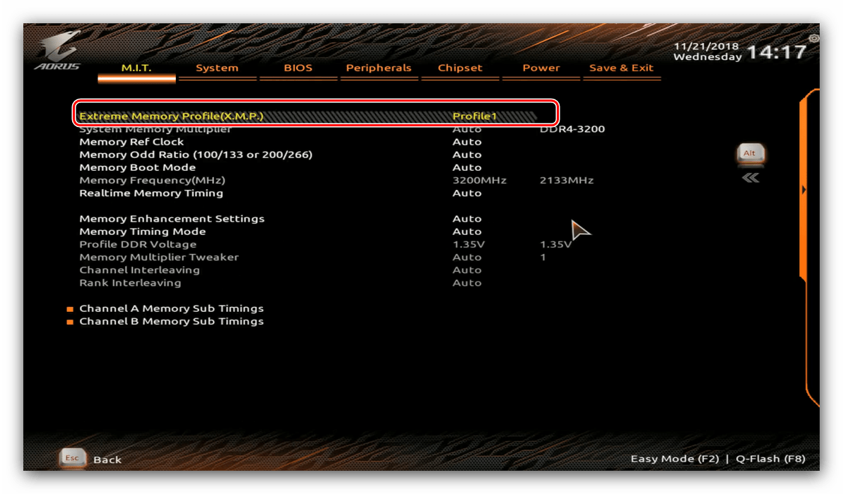
- В главном меню БИОС нажмите клавишу F2 для перехода в продвинутый режим. Откройте вкладку «M.I.T».
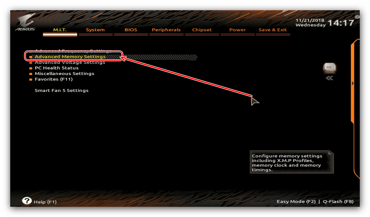
- Откройте меню «Advanced Memory Settings».
- В «Extended Memory Profile» выберите новый профиль, должен появится «Profile 1».
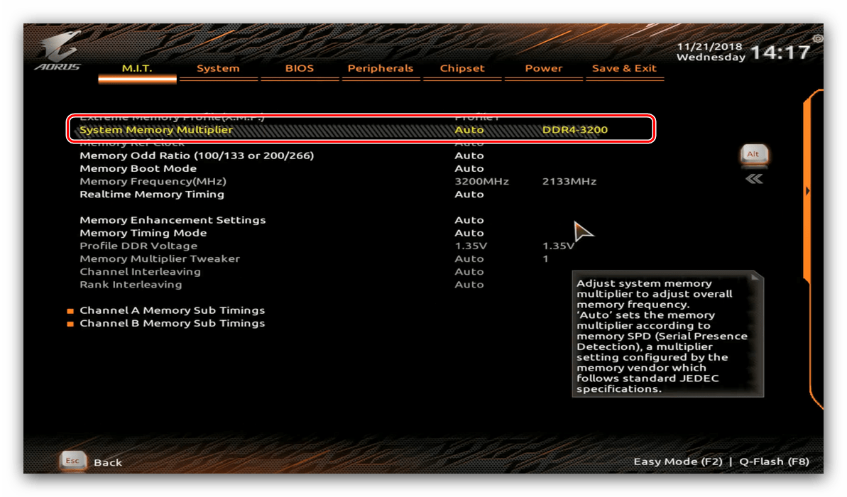
- Далее воспользуйтесь настройкой «System Memory Multiplier». Выберите в ней вариант, который соответствует конкретно вашему типу ОЗУ.
- Остальные опции можно оставить по умолчанию, однако по желанию можно открыть меню «Channel Memory Subtimings» вручную прописать тайминги для каждого из используемых каналов.
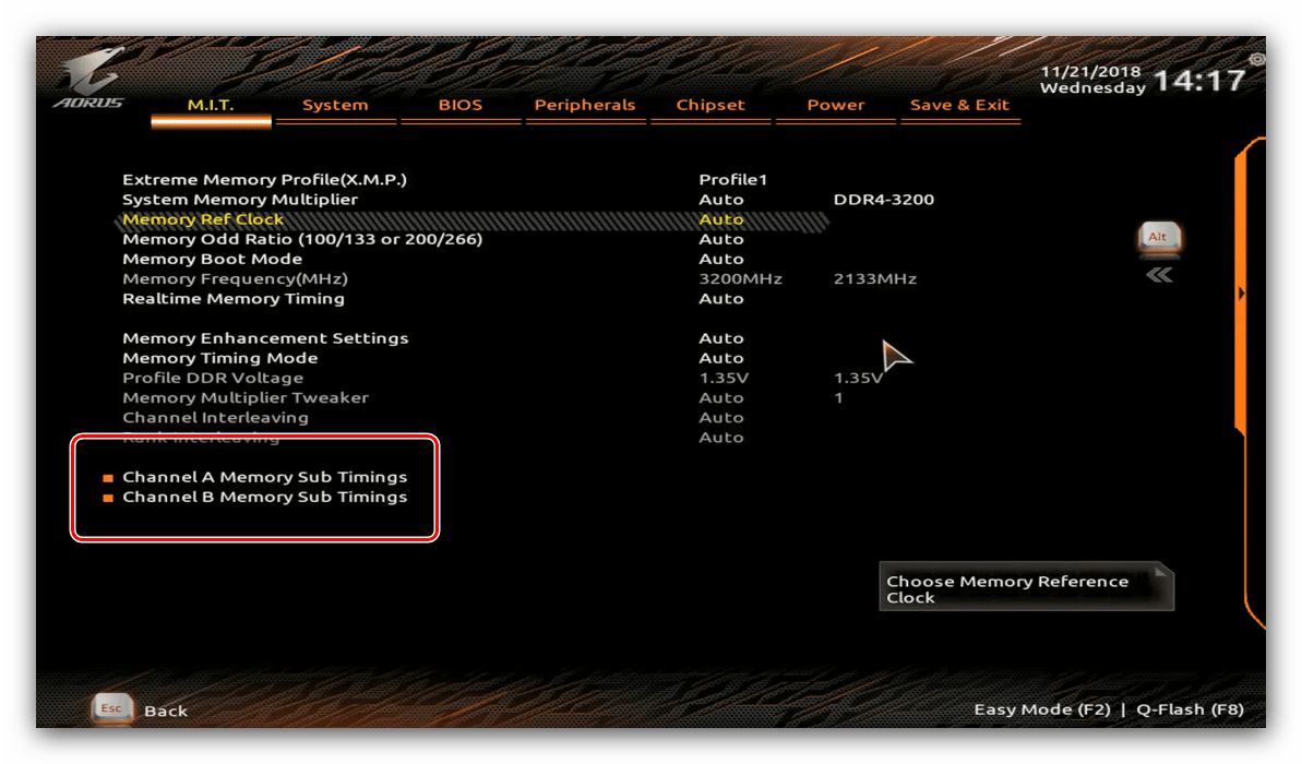
- Используйте клавишу F10 для сохранения введённых параметров.
MSI
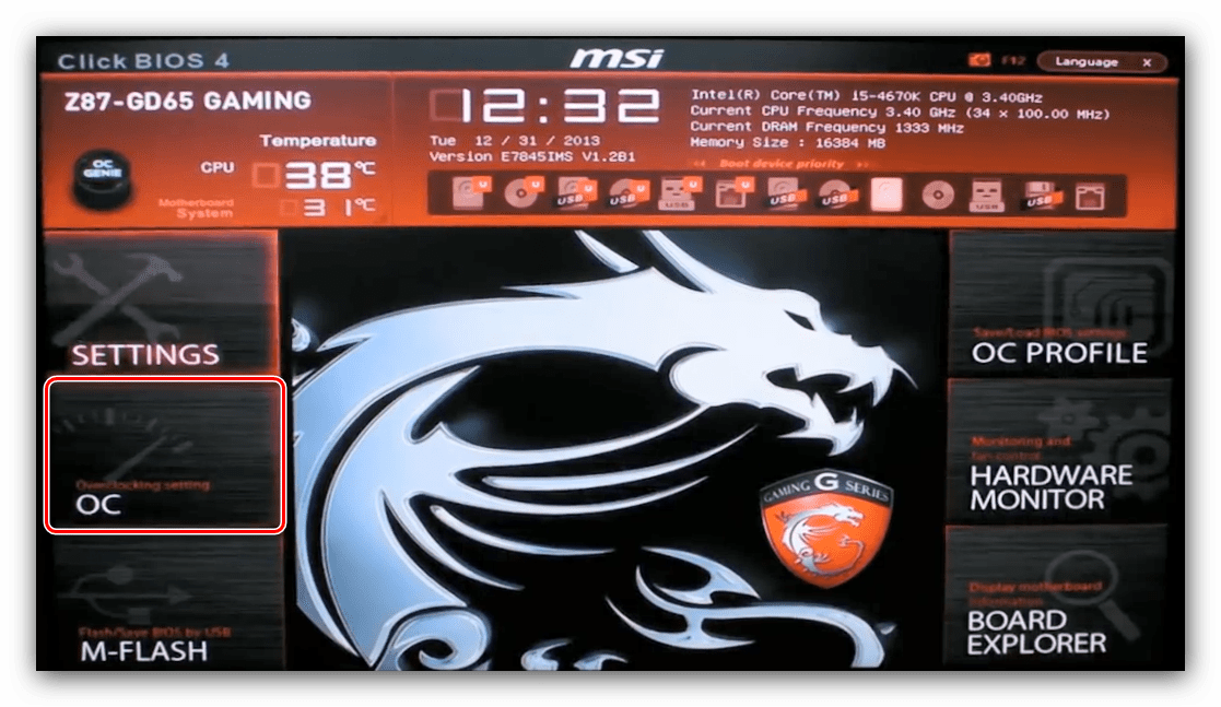
-
Воспользуйтесь кнопкой F7, чтобы открыть расширенный режим настроек. Используйте пункт меню «OC».
Заключение
На этом заканчиваем описание методов настройки частоты оперативной памяти через разнообразные BIOS. Напоследок ещё раз напоминаем – изменять эти параметры следует только в том случае, когда вы хорошо понимаете, что делаете.
Как проверить совместимость оперативной памяти и материнской платы

Оперативная память (ОЗУ) – один из основных комплектующих любого компьютера. Именно от оперативной памяти зависит, сколько программ вы сможете запустить одновременно, не сталкиваясь с серьезным замедлением работы системы.
Поэтому при апгрейде компьютера очень часто встает вопрос об увеличении объема оперативной памяти.
Но, для того чтобы увеличить объем оперативной памяти ее нужно правильно подобрать. В данной инструкции мы расскажем о том, как проверить совместимость оперативной памяти и материнской платы и узнать какие модули ОЗУ подходят.
Что влияет на совместимость ОЗУ и материнской платы

Модули DDR, DDR2, DDR3 и DDR4
Есть несколько характеристик, которые ограничивают совместимость материнских плат и модулей оперативной памяти. Это очень простые и понятные характеристики, поэтому разобраться в этом не сложно. Ниже мы рассмотрим все эти характеристики и дадим им короткое определение.
- Тип ОЗУ. В современных компьютерах применяется оперативная память типа DDR. Но, с момента появления данного типа было выпущено 4 версии DDR, которые никак не совместимы друг с другом. Это DDR, DDR2, DDR3 и DDR4, а в ближайшие несколько лет появится еще и DDR5. При этом материнские платы могут работать только с каким-то одним типом. Например, если материнская плата рассчитана на работу с DDR2, в нее можно установить только DDR2. Поэтому при проверке совместимости материнской платы и оперативной памяти в первую очередь нужно обращать внимание на тип оперативной памяти и уже после этого рассматривать все остальные характеристики.
- Тактовые частоты. Любая материнская плата рассчитана на использование ОЗУ с определенными частотами. Например, для DDR3 это могут быть частоты 1333/1600/1866/2133 МГц. При проверке совместимости необходимо убедиться, что модули оперативной памяти и материнская плата поддерживают одни и те же частоты, иначе возможны проблемы. Если приобрести модули с более высокими частотами, чем поддерживаемые платой, то в большинстве случаев все будет работать нормально. Оперативная память просто запустится на более низкой частоте, но при покупке более медленных модулей система может не заработать. Поэтому при выборе также нужно обращать внимание и на тактовые частоты.
- Максимальный объем ОЗУ. Еще одно ограничение – это максимальный объем оперативной памяти, который поддерживается материнской платой. Обычно современные мат. платы для настольных компьютеров поддерживают 8, 16, 32 или 64 Гб. Если вы попытаетесь установить больший объем, то система не заработает. При этом не важно, если свободные слоты для установки модулей. Например, если ваша система поддерживает 8 Гб и у вас уже установлено 2 модуля по 4 Гб, то установить еще 2 модуля нельзя, даже если на плате доступно 4 слота под память.
- Количество разъемов под память (DIMM). В современных материнских платах для настольных компьютеров обычно доступно 2 или 4 разъемов под оперативную память. При этом нет никакой возможности установить больше модулей, если доступно 2 разъема, значит только 2 модуля. Здесь никаких вариантов для расширения.
Как проверить совместимость ОЗУ и материнской платы
Фактически есть только один способ проверки совместимости материнской платы и оперативной памяти, это обращение к техническим характеристикам материнской платы на официальном сайте производителя. В технических характеристиках платы всегда будет указано, какой тип ОЗУ поддерживается (DDR, DDR2, DDR3 или DDR4), какие тактовые частоты (например: 1333, 1600, 1866, 2133 МГц), а также количество разъемов. Исключений здесь нет, данная информация всегда доступна. Если вы не можете ее найти, значит вы где-то не там смотрите.
Алгоритм поиска технических характеристик материнской платы очень простой. Для начала вам нужно узнать точное название платы и ее производителя. Если компьютер работает, то можно установить программу CPU-Z. Здесь на вкладке «Mainboard» будет указана вся необходимая вам информация. В строке «Manufacturer» будет указан производитель, а в строке «Model» – модель материнской платы. Если же ваш компьютер не работает, то название материнской платы можно посмотреть непосредственно на самой плате.

После того как вы узнали название производителя и модель, эту информацию нужно вбить в поисковую систему, например, в Google. Дальше просматривает результаты поиска и находим страницу, которая будет вести на официальный сайт производителя. Например, если ваш производитель это ASUS, то вам нужно найти страницу, ведущую на сайт ASUS.COM.

На сайте производителя материнской платы нужно перейти в раздел «Характеристики» или «Specifications» и найти там информацию о совместимости с оперативной памятью.

Здесь будет указанно количество разъемов под память (DIMM), максимальный объем, тип и тактовые частоты. Используя эту информацию, вы сможете без труда подобрать к вашей материнской плате совместимую оперативную память.
Другие возможные проблемы с совместимостью
Также нужно отметить некоторые другие проблемы с совместимостью оперативной памяти, которые могут вам встретиться в некоторых ситуациях.
Biostar H61MHV2 Manual
This equipment has been tested and found to comply with the limits of a Class B digital device, pursuant to Part 15 of the FCC Rules. These limits are designed to provide reasonable protection against harmful interference in a residential installation. This equipment generates, uses, and can radiate radio frequency energy and, if not installed and used in accordance with the instructions, may cause harmful interference to radio communications. There is no guarantee that interference will not occur in a particular installation.
The vendor makes no representations or warranties with respect to the contents here and specially disclaims any implied warranties of merchantability or fitness for any purpose. Further the vendor reserves the right to revise this publication and to make changes to the contents here without obligation to notify any party beforehand.
Duplication of this publication, in part or in whole, is not allowed without first obtaining the vendor’s approval in writing.
The content of this user’s manual is subject to be changed without notice and we will not be responsible for any mistakes found in this user’s manual. All the brand and product names are trademarks of their respective companies.
Dichiarazione di conformità sintetica
Ai sensi dell’art. 2 comma 3 del D.M. 275 del 30/10/2002
Si dichiara che questo prodotto è conforme alle normative vigenti e soddisfa i requisiti essenziali richiesti dalle direttive
2004/108/CE, 2006/95/CE e 1999/05/CE
quando ad esso applicabili
Short Declaration of conformity
We declare this product is complying with the laws in force and meeting all the essential requirements as specified by the directives
Похожие публикации:
- Как войти в безопасный режим
- Как настроить обс чтобы не лагал стрим
- Как получить права администратора в windows 7 без прав администратора
- Как установить msu групповыми политиками